This page provides a few examples and templates for various analyses that are available from the autoCircuits SPICE interface. For each example, a problem statement is provided together with the associated circuit diagram and the corresponding SPICE netlist. The latter can be directly copied-and-pasted into the input netlist field. For a detailed description of syntax rules and available components and analyses, click here.
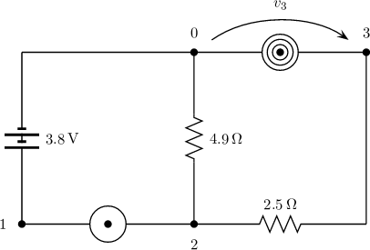
Find the voltage across resistor R_3.
V_1 1 0 dc
R_2 1 2
R_3 2 0
R_4 2 3
R_5 3 0
.DC SOLVE V(3,0)
Note: all element values are randomized.

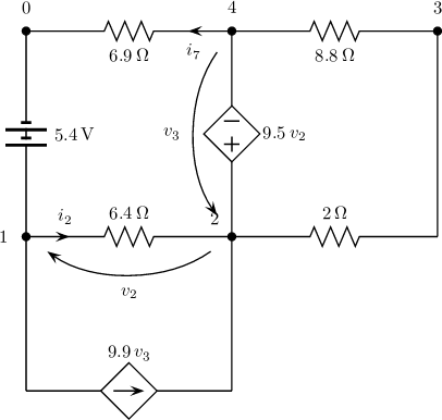
Find the current through resistors R_2 and R_7.
V_1 1 0 DC
R_2 1 2
E_3 2 4 1 2
G_4 1 2 2 4
R_5 2 3
R_6 3 4
R_7 4 0
.DC SOLVE I(R_2) I(R_7)
Note: all element values are randomized.
Find the Thevenin equivalent at port P_AB.
P_AB 1 0
R_1 1 2
F_2 2 0 R_3
R_3 2 3
V_4 3 0 DC
.DC THEVENIN P_AB
Note: all element values are randomized.

Find the AC equivalent impedance at port P_1.
P_1 1 0
C_1 1 0
R_2 1 2
L_3 2 0
.AC ZEQ P_1
Note: element values and frequency are randomized.

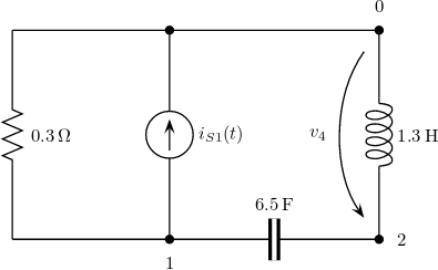
Find the voltage across inductor L_4.
I_1 1 0 AC
R_2 1 0
C_3 1 2
L_4 2 0
.AC SOLVE V(2,0)
Note: all element values are randomized.
Note: source magnitude, frequency and phase are randomized.
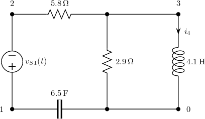
Find the AC power supplied by the voltage source.
V_1 1 0 AC
R_2 1 2
C_3 2 0
L_4 2 3
H_5 3 0 R_2
.AC POWER V_1
Note: all element values are randomized.
Note: source magnitude, frequency and phase are randomized.
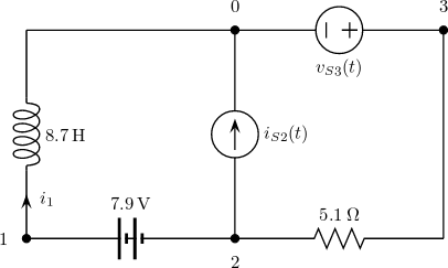
Find the steady-state current through L_1.
L_1 1 0
V_2 1 2 DC
I_3 2 0 AC
R_4 2 3
V_3 3 0 AC
.AC MULTIFREQ I(L_1)
Note: all element values are randomized.
Note: DC sources value is randomized.
Note: AC sources magnitude, frequency and phase are randomized.
Find the poles of the circuit.
L_1 1 3
V_2 1 2 DC
R_3 2 0
G_4 2 0 1 3
C_5 3 0
.LTI POLES
Note: all element values are randomized.

Find the transfer function between V_1 and I(L_4).
V_1 1 2 TF
R_2 2 3
C_3 1 0
L_4 3 0
R_5 3 0
.TF V_1 I(L_4)
Note: all element values are randomized.
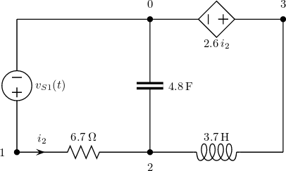
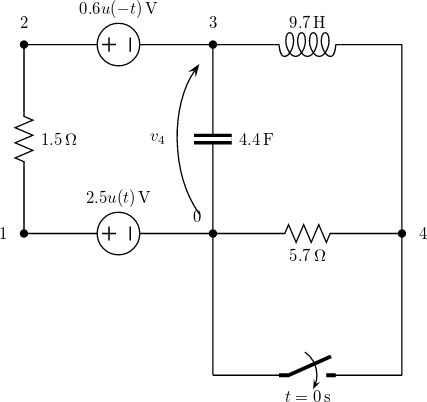
Find the expression of voltage V(2,0).
V_1 1 0 DC
R_2 1 2
S_3 2 3 S2O
R_4 3 0
C_5 2 0
.TRAN SOLVE V(2,0)
Note: element values and sources are randomized.

Find the expression of voltage V(2,0)
.V_1 1 0 DC_ON R_2 1 2 V_3 2 3 DC_OFF C_4 3 0 L_5 3 4 R_6 4 0 S_7 4 0 O2S .TRAN SOLVE V(3,0)
Note: element values and sources are randomized.
Formulate the Modified Nodal Analysis.
V_1 1 0 DC
L_2 1 2
C_3 2 0
R_4 2 0
R_5 1 2
.LTI MNA
Note: element values and sources are randomized.

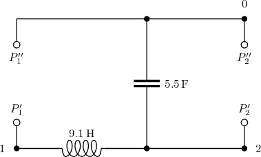
Find the impedance matrix.
P_1 1 0
P_2 2 0
L_3 1 2
C_4 2 0
.LTI ZMATRIX P_1 P_2
Note: all element values are randomized.
Find the AC Norton equivalent at terminals (A,B).
L_1 1 0
L_2 2 0
K_12 L_1 L_2
R_3 1 2
I_4 1 2 AC
P_AB 1 0
.AC NORTON P_AB
Note: all element values are randomized.
Note: coupling coefficient is randomized.
Note: source magnitude, frequency and phase are randomized.

Find the voltage V(3,0).
V_1 1 0 DC
O_2 1 2 3
R_3 2 0
R_4 2 3
.DC SOLVE V(3,0)
Note: all element values are randomized.
Note: OpAmps are represented as nullator-norator pairs.